| The main task of
my diploma thesis was, the description and implementation of one
semiconductor optical amplifier(SOA) module for "Lucent
Technologies", as an expansion of the simulation tool DICSi
(Digital Communication System Simulation). The work was done in the
programming language MATLAB. The programming language "C" was used
for time consuming program parts.
In the diploma thesis
a simple and a complicated but more exact mathematical model for a
semiconductor optical amplifier was introduced. The simple model
take into account the repletion of the amplifiers, the self phase
modulation because of temporal changes of the amplification and the
noise of the amplifiers. The more exact model taken also into
account the place and the temperature dependence of the
amplification, the multiple reflection at his front and rear side,
the inner amplifier losses as well the contribution of spontaneous
emission to the repletion of the amplifier.
Two modules for
semiconductor optical amplifier were implemented for a simple and a
resonant SOA in MATLAB as well as in C. The programming of
so-called MEX files (C-program parts which are callable directly in
MATLAB) was a successful point of the diploma thesis, because
compared with the MATLAB programs we have reached an improvement of
the computing times with a factor approx. 20.
An approximative
solution was used for the check of the implemented amplifier
models. A comparation between simulation and measuring also was
pursued. The simulation results were compared with measurement
results of the experiment at the technical University of Eindhoven
(July 1996). Similar results could by proved with
simulations.
Also a quite number of
simulation distances with several SOA's were examined. One of this
was the demonstration distance (for " CeBit 97 " ) between
Kassel-Hannover .
|
|
|
| DiCSi is a
simulation tool under MATLAB with numerous modules, and is suitable
for simulation of digitals communication systems. A simulation
model can be created with several modules. Every simulation model
can be developed in a graphical window by a block diagram. The
needed modules are selected with the help of the keyboard or by
simple mouse click. The modules for DiCSi are usually MATLAB
functions but the user can program his own modules also in C or
FORTRAN. An essential advantage of DiCSi is that all predefined
MATLAB functions and the powerful graphical interface are
available. DiCSi modules can process arbitrary long
signals.
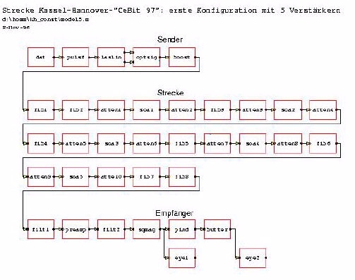
An example of a block
diagram produced with DiCSi:
|
|
|
| The transmission
length of a optical communication system is limited by the
dispersion and attenuation of the fibres on the transmission
distance. A possibility to increase the transmission length is the
application of so-called repeaters. A repeater consists of two
parts: a receiver part which transform the optical signal into an
electrical signal and one transmission part which amplifies the
electrical signal and transform it back into an optical signal. The
use of repeaters can be very cost intensive. A second possibility
for increasing the transmission length is the use of optical
amplifiers. These can directly amplify the light without previous
transformation into an electrical signal. The principle of optical
amplifiers is similarly like that one of a laser; the light is
amplified by spontaneous emission.
Some kinds of optical
amplifiers are: the semiconductor optical amplifier (SOA), the
Raman amplifier, the Brillouin amplifier, the Erbium remunerative
booster the Praseodym booster and others. Base of the Raman and
Brillouin amplifiers are the two nonlinear non elastic spreading
effects: Raman and Brillouin spread. EDFA amplifiers are ideal
components of a optical communication system for 1550 nm
wavelength. Many applications (video transmission and LAN) require
a wavelength near to 1330 nm (in the proximity of the zero
dispersion point). For the transmission by wavelengths near to 1300
nm they are two possibilities for amplification of the optical
signal: a Praseodym amplifier or a semiconductor optical
amplifier.
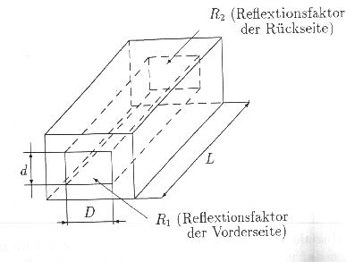
The principles of
semiconductor optical amplifiers:
A semiconductor
optical amplifier consists of an active semiconductor which is
embedded between two mirrors with the reflection factors R1 and R2.
Semiconductor optical amplifiers can be divided up into two
types:
- ideal (non resonant)
amplifiers
- resonant
amplifiers
We speak about ideal
amplifiers if the reflection factors one front and rear side R1 =
R2 = 0. Otherwise if R1 != 0 and R2!= 0 we speak about resonant
amplifiers. In this case the mirrors cause a feedback of the output
signal to the input which influences the gain of the amplifier. In
practice a non resonant amplifier doesn't exist. However we speaks
about ideal amplifiers if the reflection factors are less then
10^(-4).
The applications of
optical amplifiers are large. Optical amplifiers are used for e.g.
for power amplification on the transmission side or as
preamplifiers on the receiver side. For compensation of attenuation
loss through the fibres optical amplifiers are used as "in line"
amplifiers. Because of the bidirectional work of optical amplifiers
they are used in local networks, so-called "local area network"
amplifiers.
|
|
|
| Some
examinations for the optical communication distance
"Kassel-Hanover" takes into account the practice's desired case;
minimal configuration of the amplifiers. As an example we show the
case, in which all the in line amplifiers have the same maximal
amplification. The simulation was done for a wavelength 1312 nm
with gauss pulses of the duration of 40 ps, extinction ratio of 10
% and peak power of 25 mW. The noise figure for each in line
amplifier was 8,5 dB, "Henry" factor was 5 and the maximum laser
chirp was 40 GHz. The sampling frequency of 5,12 THz was used for a
realistic modelling of the noise.
Different distance
configurations were examined: a configuration with 4, 5 and 6
amplifiers. Below we show the DiCSi block diagram for a
configuration with 5 amplifiers. For each in line amplifier we have
chosen a maximum amplification of 12 dB. At every connecting side
of the amplifiers we have chosen a 3 dB loss.
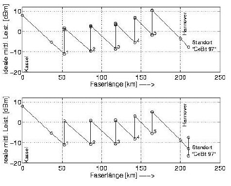
The simulated power
over the distance Kassel-Hannover:
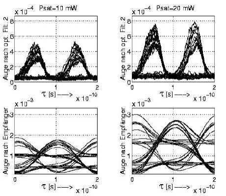
Simulated eye patterns
before and after the receiver:
|
|
|
|
|
|